


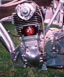
The Maely MK1 differed from the later MK2 in that it was a unit constructed engine with a wet clutch that ran in an enclosed oil bath. Of the MK1 there were three different variations, #1, #2 and #3, the first being available in 1974 and we cover these three variations on this Page of the Maely story.
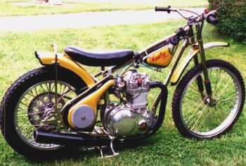
Caption: The type #1. On this engine you can find a inspection cover (secured by 4 Allen bolts for controlling the camchain tension) mounted in the side of the cylinder.
The MK1 had a crankcase that looked a bit like a strengthened version of that for a BSA Goldstar, with a rearward extension to carry the bearings for a jackshaft and clutch. But the old BSA single's crankcase was encumbered with a side compartment for its cams and tappets; the Maely engine's timing-side casting has only a shallow cavity for the sprocket and chain driving its single overhead camshaft.
There was a worm extension on the nut holding the cam sprocket, and that engaged with a gear in the side cover to drive the oil pump plungers-one pushing oil to the crank bearings, the other's output goes up to the cylinder-head. Ken was very proud of his oil pump: he said it was so flat and compact and strong that it wasn't going to get knocked off the side of the engine when some rider dropped his new Maely.
Caption:
The single overhead camshaft is shown here in place in a partially finished
head casting. It turns in rolling element bearings and works two forked
rocker-arm followers.
Maely's was also terribly pleased
with the clutch arrangement they'd worked into the design. He'd admit that
the clutch is a transplant from some big-displacement Japanese motorcycle
(he wouldn't say which) but would rather talk about its right-side mounting
position and the manner in which it's driven.
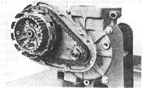
Caption:
A Morse Hy-Vo chain runs back to the wet plate clutch inside a no-grit
oil-tight case. Ken tells us the other speedway bikes were English-traditional
in this respect, with left-side primary drives and clutches, countershaft
sprockets buried behind their clutch baskets, and substantially exposed
primary chains. His right-side clutch was less apt to be damaged in a spill,
its Morse Hy-Vo chain ran fully enclosed in an oil bath, and the jack-shaft
sprocket was covered by nothing more than the three-screw plate that serves
as a guard and clutch throwout bracket.
The Maely-Motor's crank comprised
two large flywheels into which mainshafts and a crankpin were pressed.
All the journals ran in caged roller bearings. The connecting rod was made
from an aluminum forging of a type familiar to hot rodders, but left in
one piece and had a heavy steel bearing race pressed into its big-end.
The crank assembly was very massive, and its bearings wouldn't have to
contend with contaminated oil: once the oil gets past the bearings and
into the crankcase it simply puffs out on the ground via a pair of one-way
flapper valves located in a boss on the sump.
 There's an echo of technology-past in the Maely-Motor's cylinder arrangement:
the cylinder axis is offset "a little over an eighth-inch" behind the crank
centerline. Ken says this improved torque. The cylinder was an aluminum
casting, with an iron liner and an 88-millimeter slipper skirt forged Arias
piston. This bore, in conjunction with the 82mm stroke, gave the engine
a displacement of 498.7 cubic centimeters.
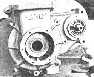
(LEFT:) The cam chain wraps over a crank sprocket inside this case cavity, which has the twin-plunger oil pump built into its cover. Oil leaves the crankcase through flapper valves in an extension on the sump's base.
Pistons of different crown heights were available, to provide compression ratios from 10.5:1 up to 13.5:1. If the Maely-Motor cylinder head looks
familiar, it is because its design was inspired by the Honda XL350-which also provided most of the actual parts. Still, it wasn't just a made-in-America
Honda cylinder head. Jerry Branch took advantage of Maely's intention to cast a new head to do a massive reworking of the ports, and it was discovered while
flow-testing an XL350 head bolted over an 88mm cylinder that the larger bore alone gave an immense increase in flow capacity. . . by unshrouding the paired
valves at their sides. Further flow improvement was gained by giving the intake port a steep downdraft angle, and Branch said bulk flow should be more than
adequate in the Maely 500 even though its head uses Honda 350 intake and exhaust valves.
The best aspect of the above expedient was that Ken Maely didn't have to spend a fortune developing his own valve gear, and customers were be able to find many replacement parts at the nearest Honda dealership.
(RIGHT): The type #2 (1973). The second type of the MK1 is without the inspection cover but has normal cooling fins for head and cylinder.
Not only that, but the multitude
of trick (i.e. performance) parts made for the XL350's top end could be
used in the Maely-Motor. The single, very important difference between
Honda and Maely valve gear was that Ken opted for needle roller and ball
bearings at the camshaft journals instead of Honda's load-limited and lubrication-sensitive
plain bearings.
Some thought the Maely-Motor's CDI magneto was a "Krober." They'd be wrong, but the mistake would be entirely understandable because the capacitor-discharge system in question is very nearly a wire-perfect copy of a Krober. It happens that Ken Maely had yet another good friend in the electronics business, and he supplied Ken with Krober look-alikes. The Mikuni carburetor wasn't a copy; it was the real thing, with a 38mm throat and with all its fuel passages reworked for use with alcohol. Maely's merry men drilled a flock of spill holes in the Mikuni float-needle body, fitted outsized main and needle jets with the appropriate throttle slide and jet needle, and had a carburetor that worked exceedingly well on any alcohol- fueled, 500cc speedway engine.
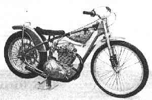
Left: is the lovingly restored Type #1 machine formerly owned by Bob Allan that now resides in the Museum owned by Rick Newlee. This was actually the third ever to be built by Ken, and being a special order was the only one like it.